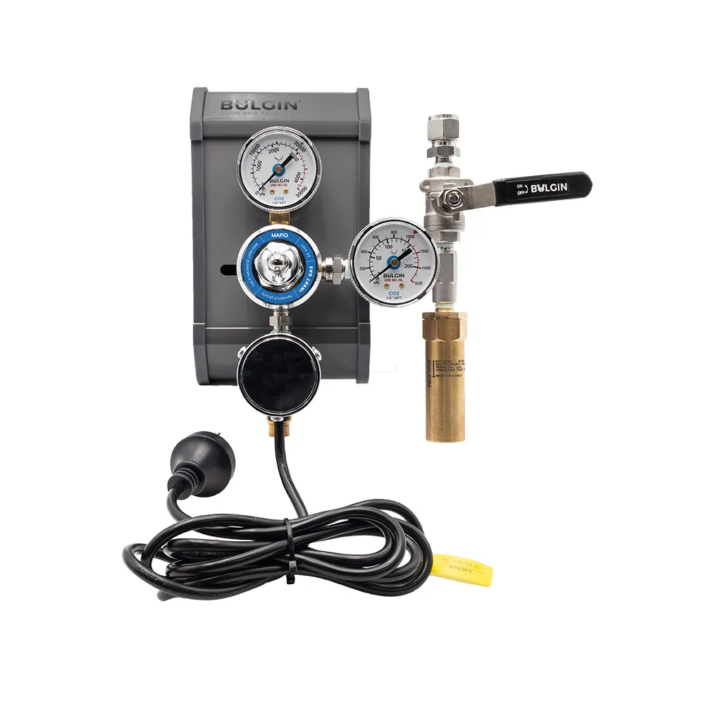
The Bulgin® MAPiQ Gas Distribution Panel is a purpose-built gas control assembly designed to regulate and distribute compressed food-grade modified atmosphere packaging (MAP) gases from a cylinder or cylinder pack to downstream food packaging equipment.
Designed for professional food and beverage applications, the panel combines the key pressure-control and safety components required for a practical MAP gas supply system, including a high-pressure inlet assembly, pre-gas heater, lockable primary regulator, outlet pressure gauge, safety relief valve, non-return protection and outlet isolation valve.
The system is suitable for food-grade CO₂, N₂ and O₂ modified-atmosphere gas mixtures and provides a regulated outlet pressure range of 0–1,000 kPa, with nominal gas supply capacity of up to 20 m³/h, subject to operating conditions.
Key Features
-
Designed for Modified Atmosphere Packaging gas distribution
-
Suitable for food-grade CO₂, N₂ and O₂ gas mixtures
-
Maximum panel inlet pressure of 20,000 kPa (200 bar)
-
Adjustable outlet pressure from 0–1,000 kPa
-
Nominal gas supply capacity up to 20 m³/h
-
Lockable primary regulator pressure setting
-
Integrated high-pressure 190 W pre-gas heater
-
Safety relief valve protecting the low-pressure section
-
Stainless steel non-return valve for backflow protection
-
Outlet pressure gauge for visual pressure monitoring
-
Manual outlet isolation valve
- 1/2" tube panel outlet
-
Available with 1 m, 2 m or 3 m high-pressure supply hoses
-
Compatible with Type 10, Type 30 and Type 50 cylinder connections through the appropriate hose assembly
Designed for MAP Gas Supply
Modified atmosphere packaging systems rely on a controlled gas supply to deliver the required gas mixture to the packaging machine.
The MAPiQ Gas Distribution Panel provides a centralised interface between the high-pressure cylinder or cylinder pack and the downstream packaging equipment. The high-pressure section operates from the cylinder connection through to the regulator inlet, while the downstream low-pressure section operates from the regulator outlet through to the panel outlet.
This configuration allows the packaging equipment to receive a controlled gas supply while incorporating dedicated pressure monitoring, backflow protection, pressure relief and isolation functions within the panel.
Pre-Gas Heating for High CO₂ Applications
The panel incorporates a 190 W, 220 V, 50 Hz pre-gas heater with a manufacturer-stated heating range of 45–60°C.
The heater is positioned within the high-pressure supply section and is intended for applications with high CO₂ content, assisting gas delivery during pressure reduction.
This can be particularly useful where significant pressure reduction and CO₂ concentration may otherwise contribute to substantial cooling within the gas supply system.
Integrated Safety & Gas Control
The low-pressure section of the panel is protected by a safety relief valve with a nominal set pressure of 1,300 kPa. The relief valve is specified with a rated discharge of 3,400 L/min of air at 1,625 kPa and is identified in the specification as AS 1271-3 Class A.
A 316L stainless steel check valve with EPDM sealing provides backflow protection. The check valve has a cracking pressure of 6 kPa, bubble-tight leakage rating and Cv of 0.1.
The outlet section also incorporates a manual stainless steel isolation ball valve, allowing the downstream gas supply to be isolated as required.
Technical Specifications
|
| Product | Bulgin® MAPiQ Gas Distribution Panel |
| Part Number | 379-15001 |
| Intended Gas Service | Food-grade CO₂, N₂ and O₂ MAP gas mixtures |
| Maximum Panel Inlet Pressure | 20,000 kPa (200 bar) |
| Inlet Connection | G3/8" RH |
| Cylinder Connections | Type 10, Type 30 and Type 50 via hose assembly |
| Available Hose Lengths | 1m, 2m and 3m |
| Regulated Outlet Pressure | 0–1,000 kPa |
| Nominal Gas Supply Capacity | Up to 20 m³/h* |
| Primary Regulator | Lockable pressure setting |
| Outlet Pressure Gauge | 0–1,600 kPa |
| Safety Relief Valve Set Pressure | 1,300 kPa |
| Pre-Gas Heater | 190 W, 220 V, 50 Hz |
| Heater Range | 45–60°C** |
| Backflow Protection | 316L SS check valve, EPDM |
| Check Valve Cracking Pressure | 6 kPa |
| Outlet Isolation | 1/4" NPT ball valve |
| Panel Outlet | 1/2" tube |
High-Pressure Supply Hose
The panel can be supplied with 1m, 2m or 3m high-pressure flexible hose assemblies.
The specified hose incorporates:
- 316L stainless steel inner core and end fittings
- 304 stainless steel outer braid
-
External stainless steel anti-whip/protection spring
-
Maximum working pressure of 30,000 kPa
-
Manufacturer-stated service temperature range of -200°C to +426°C
Cylinder connection assemblies can be configured with Type 10, Type 30 or Type 50 nut and stem connections depending on the required MAP gas supply.
Primary Pressure Regulation
The panel's primary regulator is designed for a maximum panel inlet pressure of 20,000 kPa and provides an adjustable outlet pressure of 0–1,000 kPa.
The regulator incorporates a lockable pressure setting, helping maintain the selected operating pressure once commissioned. The specification identifies a chrome-plated brass construction with a PTFE seat and neoprene diaphragm, with the regulator specified to AS 4267.
Typical Applications
-
Modified Atmosphere Packaging systems
-
Food tray sealing equipment
-
Gas flushing packaging systems
-
Packaging lines using CO₂, nitrogen or oxygen-containing MAP mixtures
-
Food processing facilities
-
Centralised packaging-machine gas supplies
-
Cylinder and cylinder-pack supplied MAP installations
Connection & System Configuration
The MAPiQ panel is designed as the gas-control interface between the high-pressure supply and the downstream packaging machine.
A typical system arrangement is:
Cylinder / Cylinder Pack → High-Pressure Hose → Pre-Gas Heater → Primary Regulator → Check Valve → Pressure Gauge / Safety Relief → Isolation Valve → 1/2" Tube Outlet → Packaging Equipment
The packaging machine's required pressure, flow and process settings must be configured by the appropriate machine specialist in accordance with the packaging equipment manufacturer's requirements.
Note: Nominal gas supply capacity is up to 20 m³/h, however actual available flow will depend on inlet pressure, selected delivery pressure, gas composition and confirmed heater performance. Downstream packaging-machine pressure, flow and process requirements must be confirmed for the specific equipment and application before installation.